
Crafted Vibes: From Concept to Kickass RC Car
I crafted a unique circuit board for a remote-control car as part of an Electronics Lab challenge. I used an electric skateboard base, repurposed motors, and a 433MHz RF module for the remote, culminating in a cool, self-designed PCB after many tweaks and trials.
In my sophomore Electronics Lab, our TA threw down the gauntlet: each of us had to cook up a unique circuit board – from logic design, layout, to PCB production. And, heck, I love a good hands-on, crafty challenge! With the TA giving us total freedom (just had to be our own creation), I was good to go. With my left hand experimenting on a breadboard and my right hand diving deep into the internet, knowledge was just a click away.
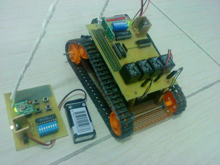 Results
Now, who can resist a kickass remote-control car? To amp up the cool factor, I went off-road and used an electric board as the base, channeling mad tank vibes. For the control system, I repurposed those old-school Tamiya motors from our childhood slot cars. A simple flip of the current direction, and bam – we got forward and reverse. Threw in the ULN2803 driver IC to manage the relays, and we were in business.
The cherry on top? The remote control. Thanks to the wonder of the web, I stumbled upon a 433MHz RF transmitter-receiver module, usually reserved for garage doors – but now it was serving my RC car ambitions. Muahaha!
After countless tweaks and trials on the breadboard, my car was joyriding remotely. But the game wasn’t over – I needed to design an actual PCB. Enter OrCAD, the PCB design MVP. With its help, I laid out the blueprint and tailored the board details, like adjusting line width for the high-current motor demands. Then came the PCB production phase: exposure and etching, imprinting my design on the photosensitive board and dissolving away the rest. Sure, it took a ton of trial and error to get a sleek PCB, but that’s a tale for another day. Now, feast your eyes on my epic creation!