Crafting Time: My Tokyo Adventure with Salvaged Tech
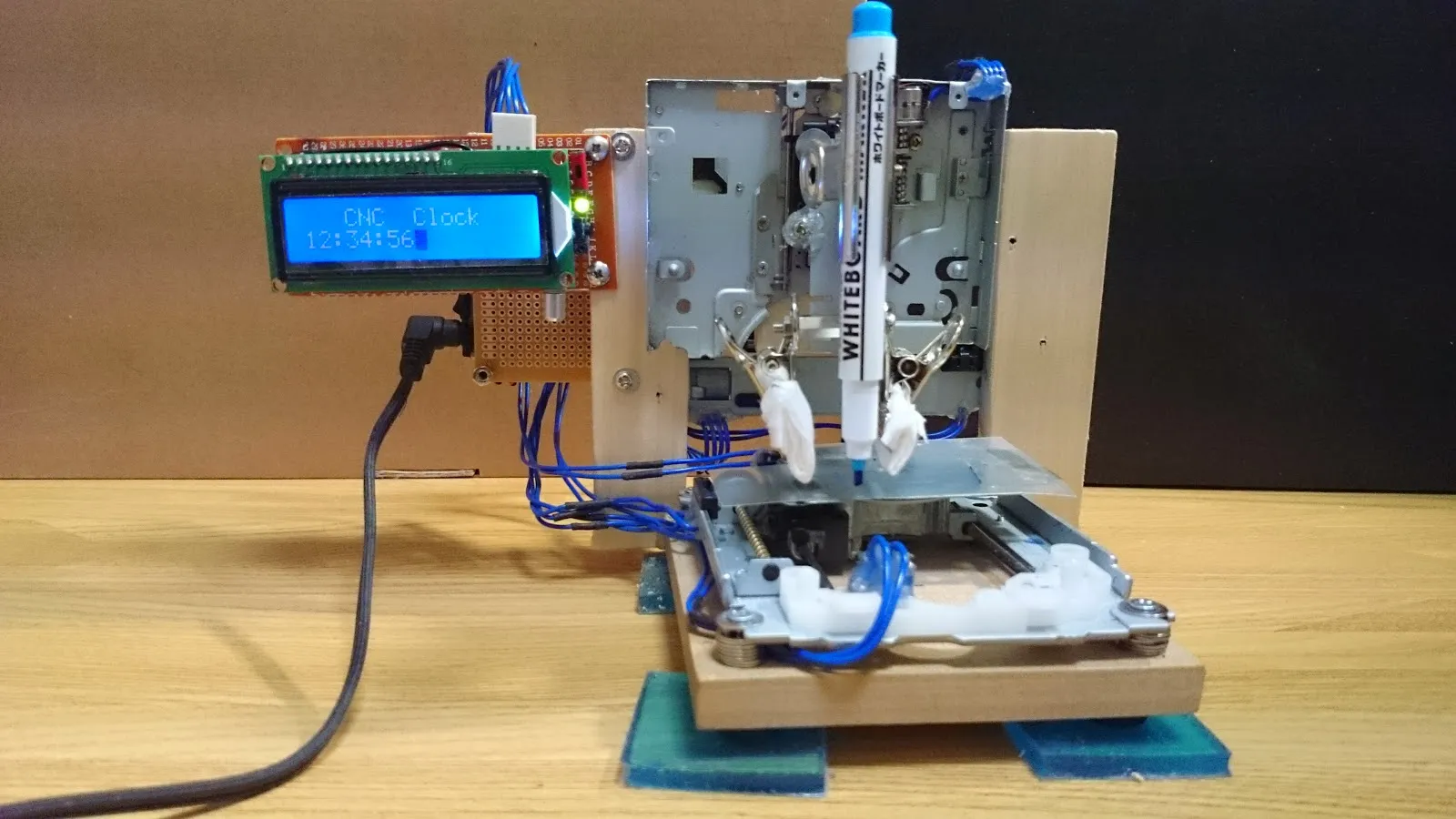
I recount cobbling together a CNC clock from salvaged tech during my time in Tokyo. Inspired by Iron Man, I turned recycled parts into a time-scribing machine with a cool, industrial edge
“Tony Stark was able to build this in a cave! With a box of scraps!” - That iconic line from Iron Man had me shook as a kid. Sure, creating something fancy with top-notch components is cool, but crafting something legit with random pieces? Now that’s where the real skill shines.
During my exchange year in Tokyo at ‘The University of Electro-Communications (UEC)’, I stumbled upon this goldmine – a 3C recycling hub on campus. You name it, from computers, oscilloscopes, to printers, they had it. Many were ditched just for being vintage, yet they were still in prime working condition. That’s when it hit me: why not channel my inner Stark and craft a toy using these salvaged parts?
So, I scavenged heaps of CD-ROMs, Floppies, all to harness their stepper motors. My vision? A Computer Numerical Control (CNC) machine that scribes time – imagine a clock with a rugged, industrial vibe. Total game changer. During my time in Tokyo, I was armed with just a laptop, missing out on all the essential tools like an oscilloscope for firmware development. All I managed to borrow from my lab mates were a multimeter, soldering iron, and a drill. Anything I lacked tool-wise, I compensated with sheer grit, innovation, and some mad development skills. Let’s just say, my Tokyo adventure turned out to be a masterclass in making do with what you’ve got.
Demo
Materials
- CD-ROM *2
- Floopy *2
- LCD1602 *1
- Ardunio NANO*1
- ATMEGA328P *1
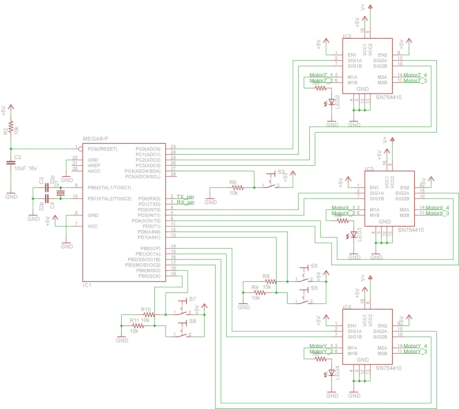
- SN754410 *3
- Switches from CD-ROM *5
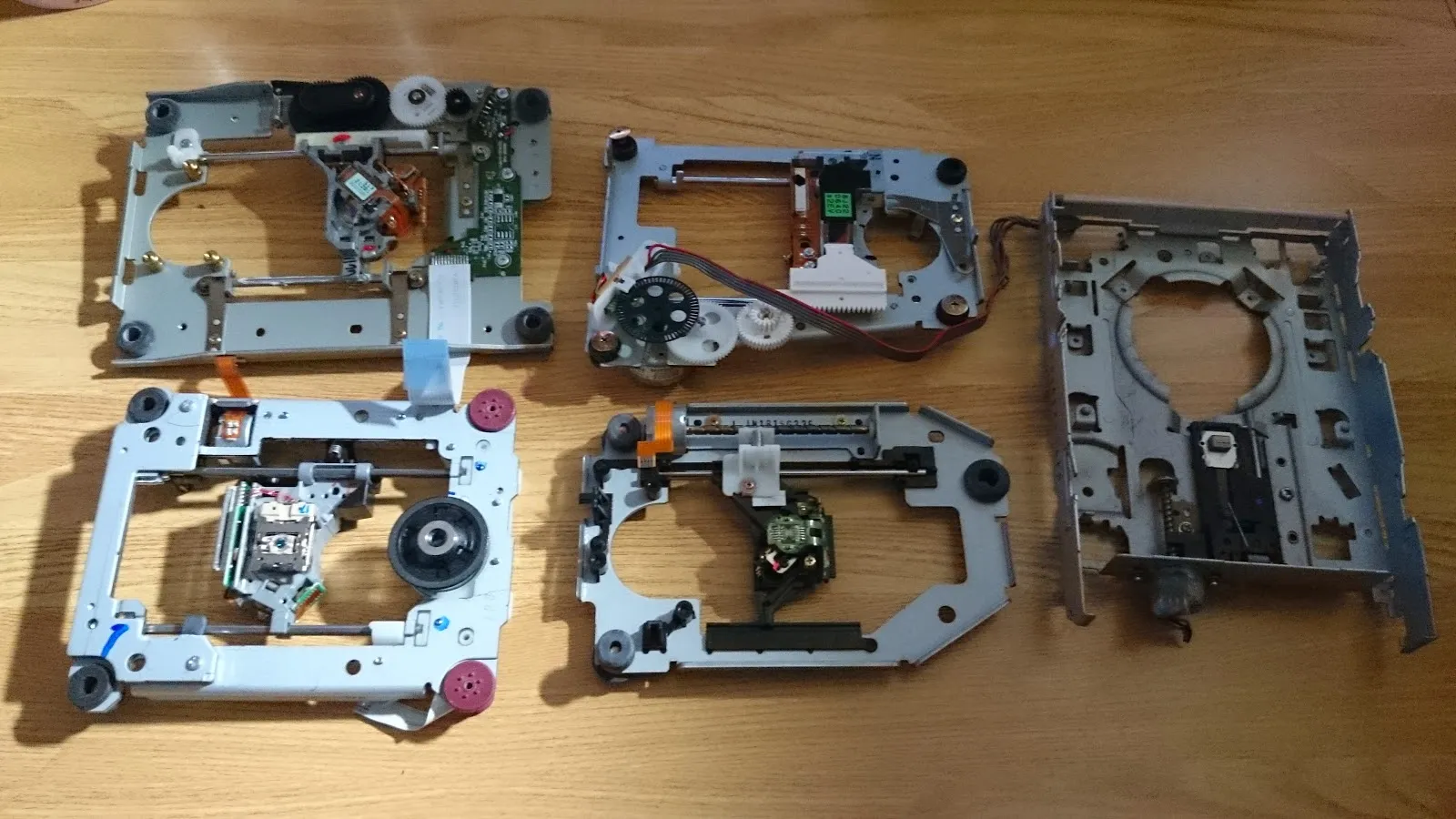
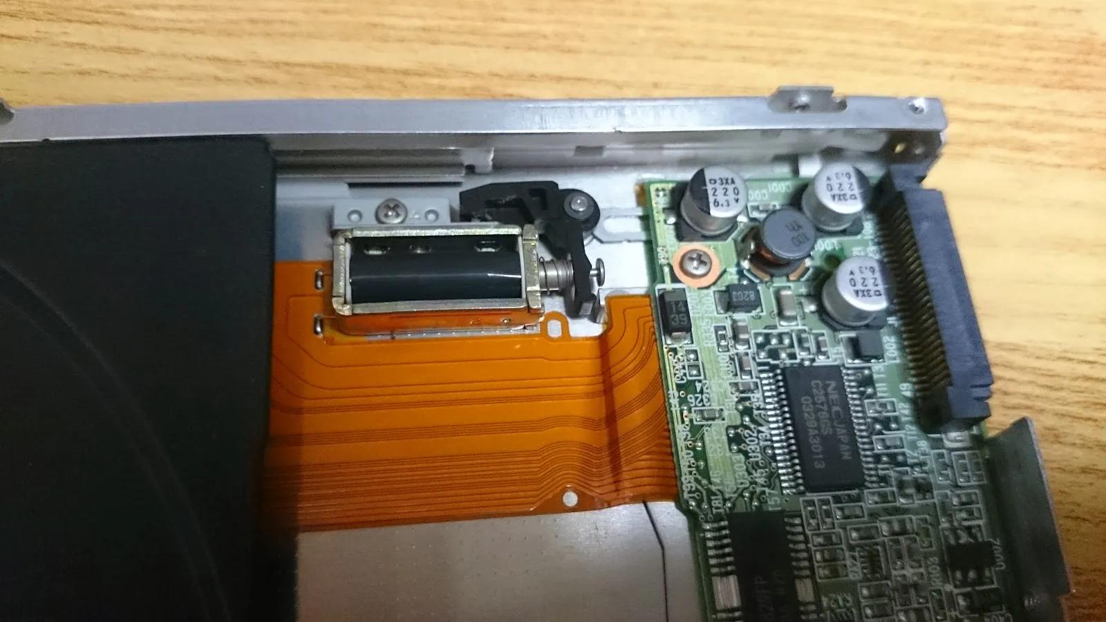
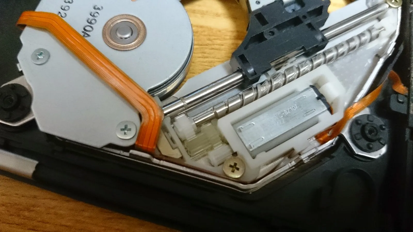
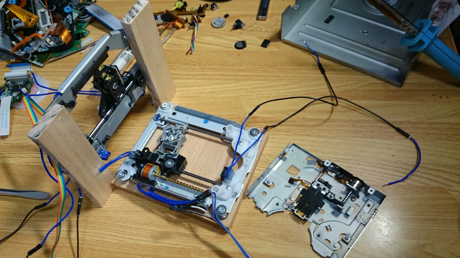
Disassemble
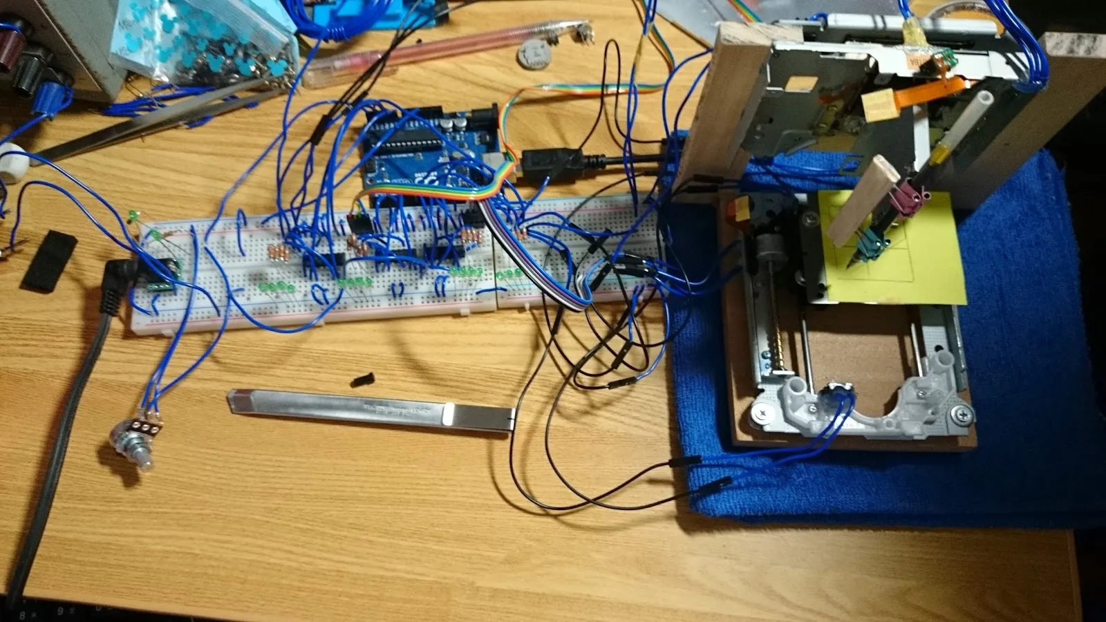
Just get the important parts and make some fun with it.
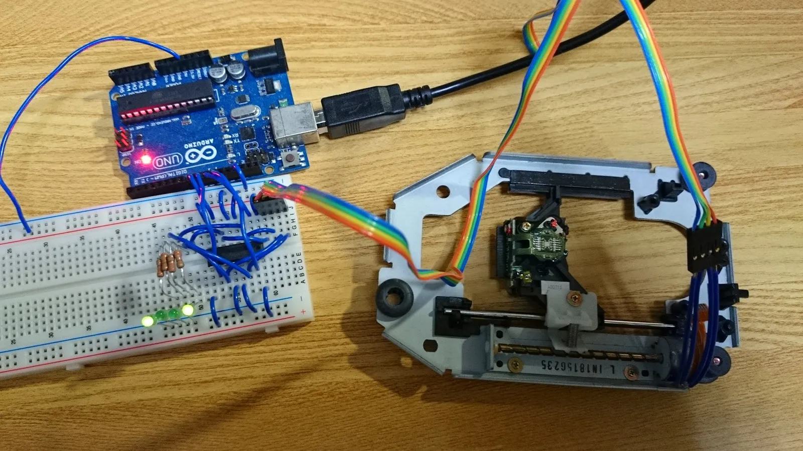
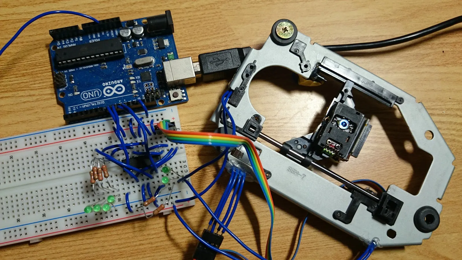
Simple Experiments
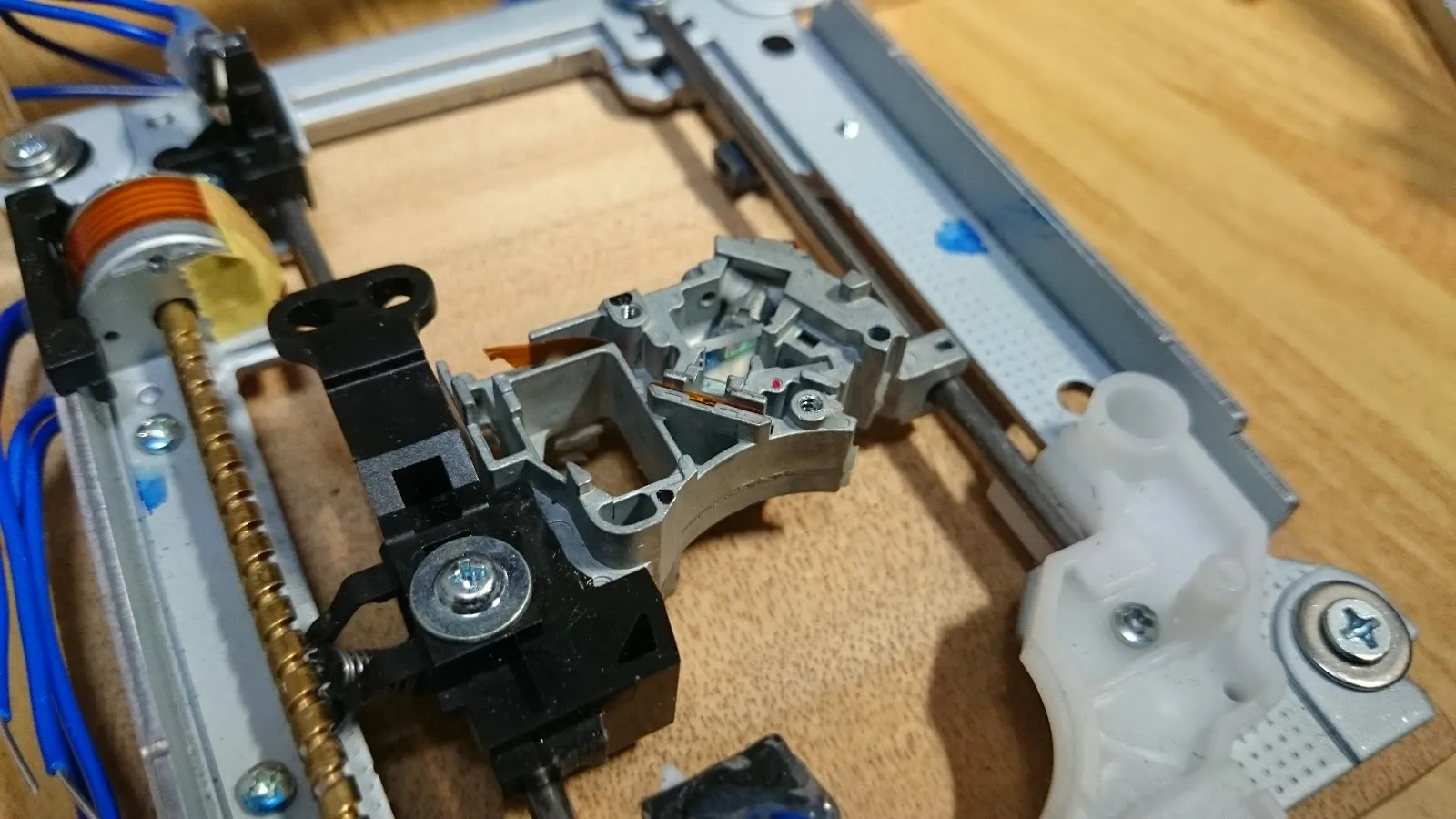
Tuning stepper motor controller and test limit protections
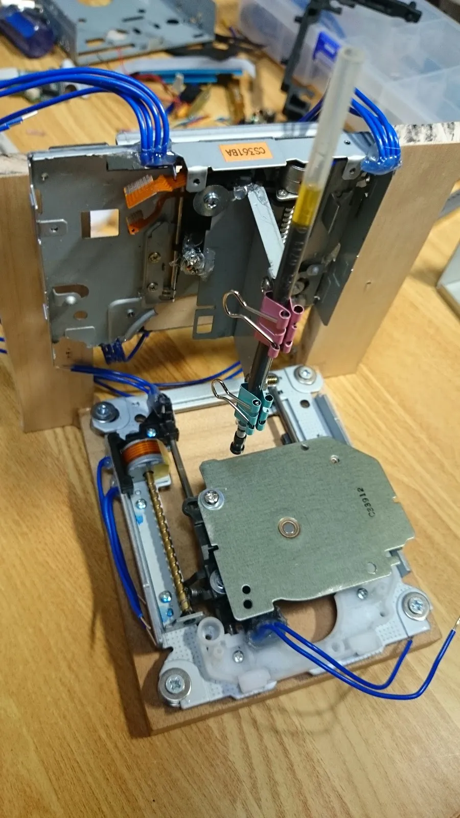
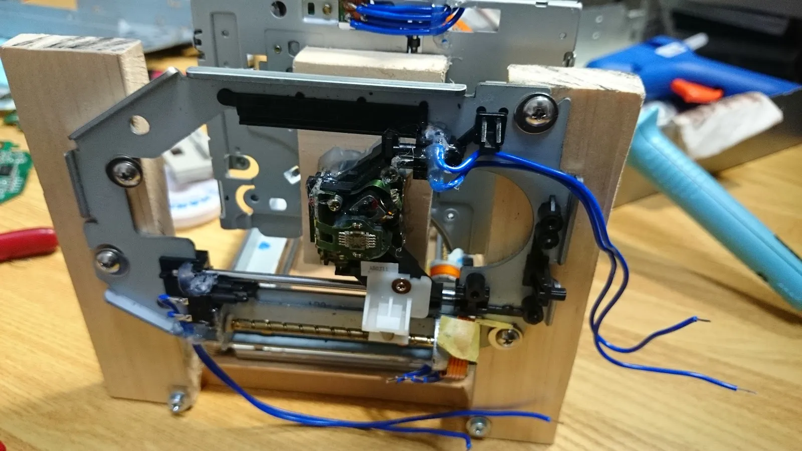
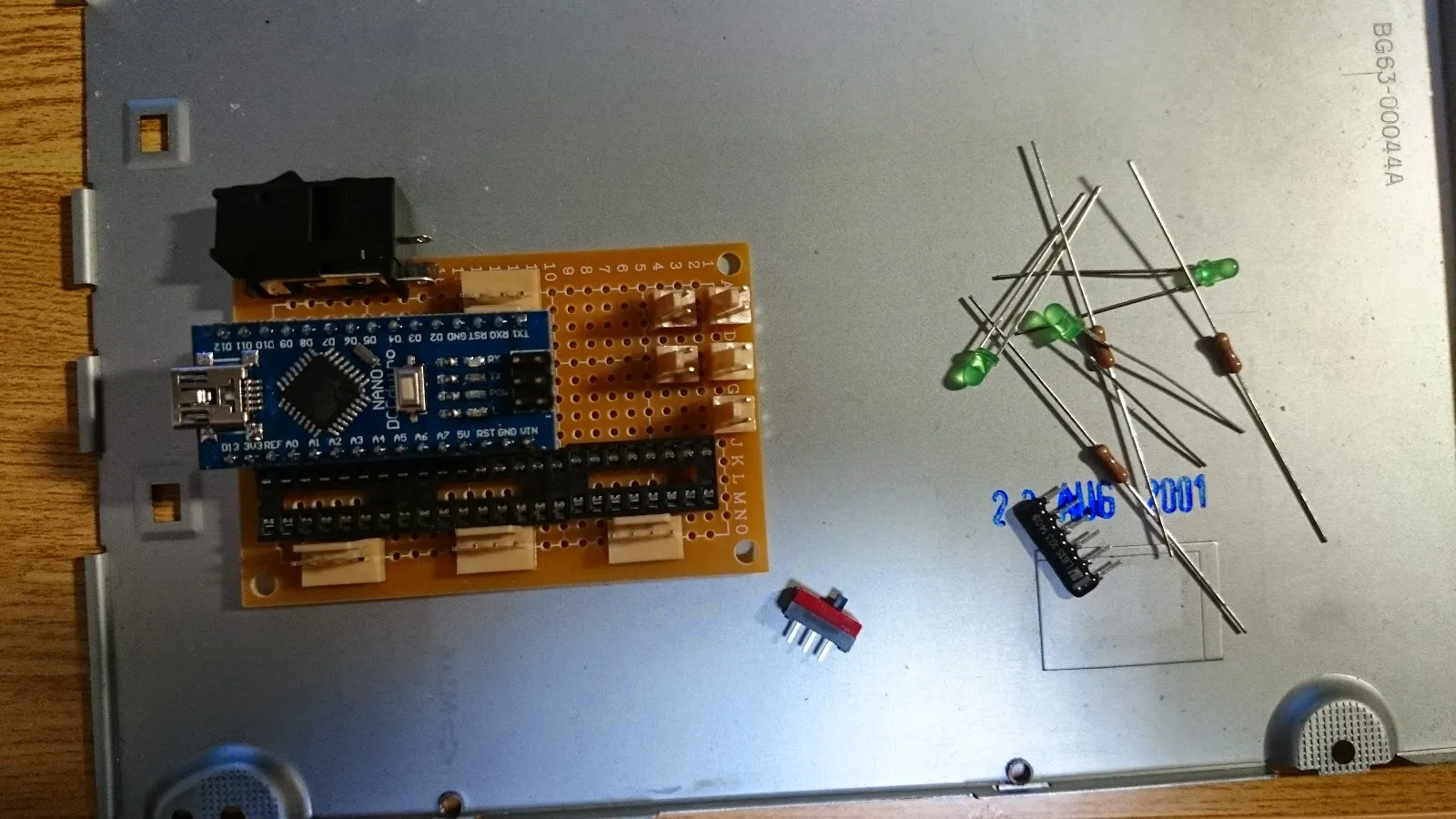
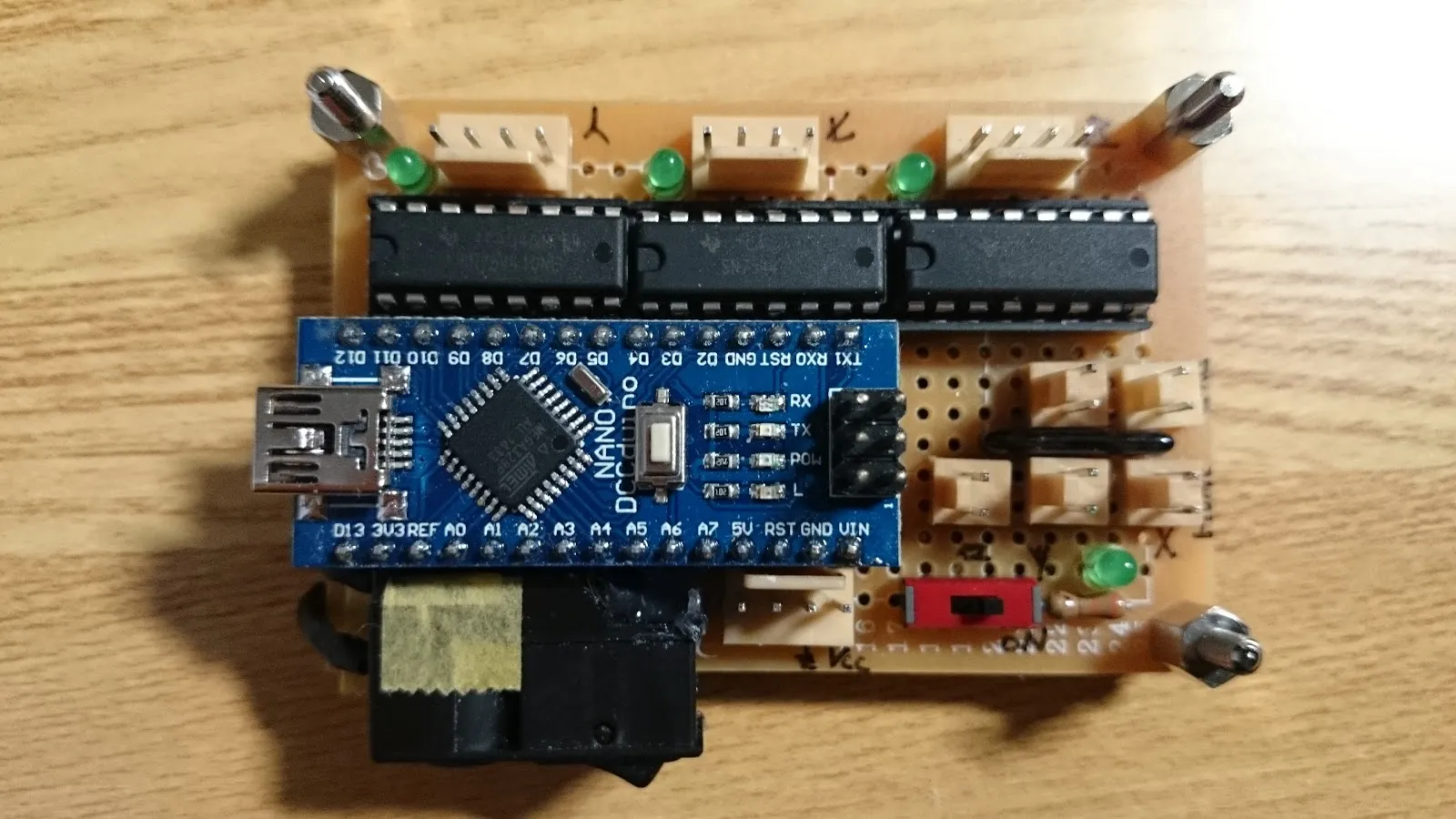
Assemble
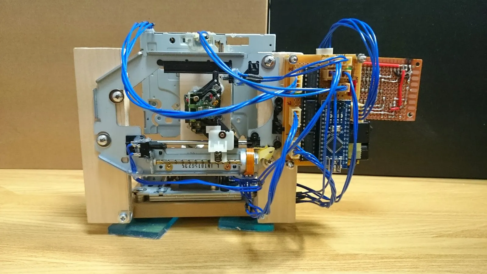
Put hardware parts all together
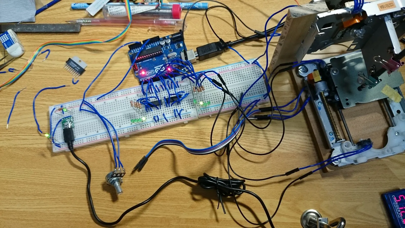
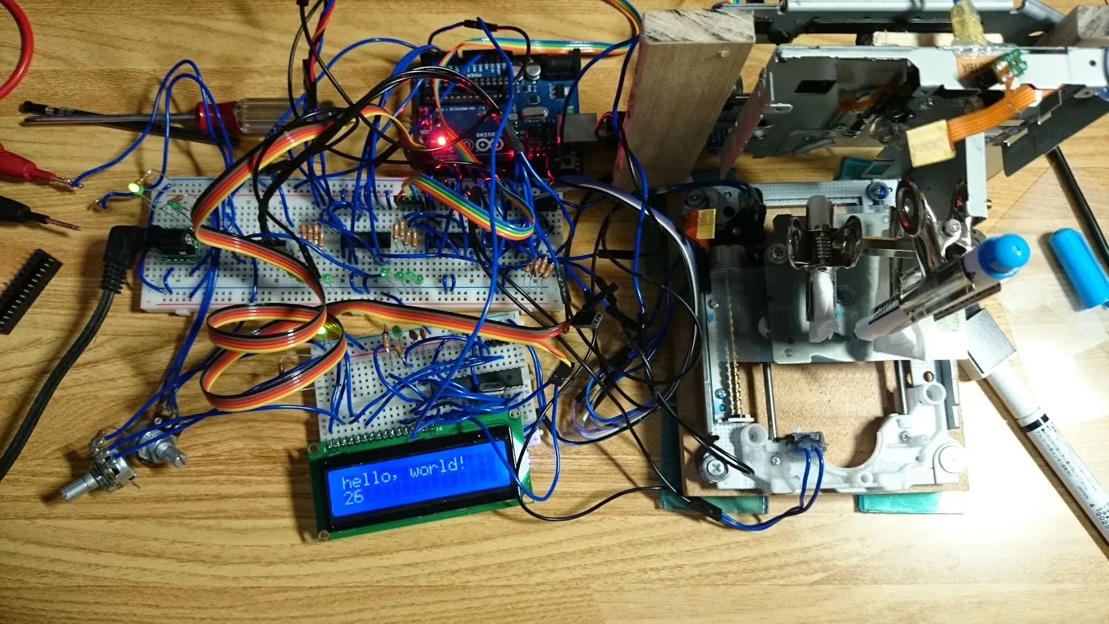
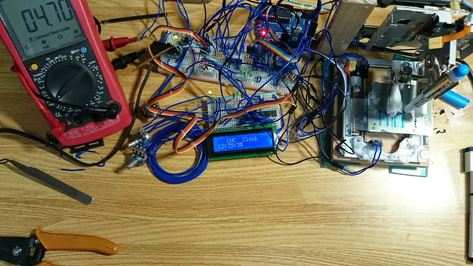
Full Code Experiments
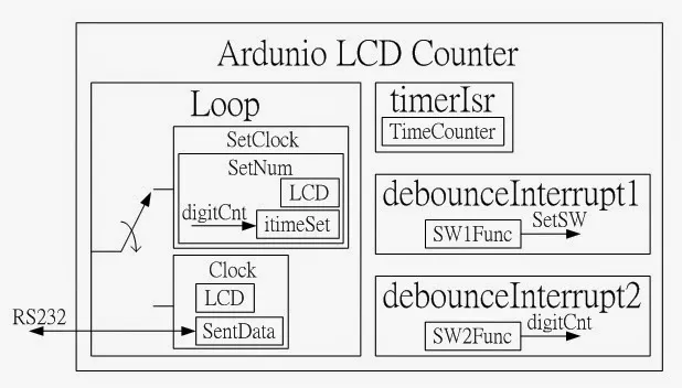
Control X, Y, Z axis in the same time with LCD control in separate MCU
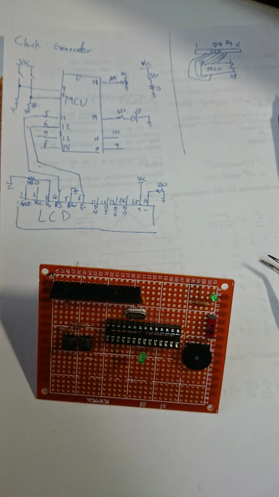
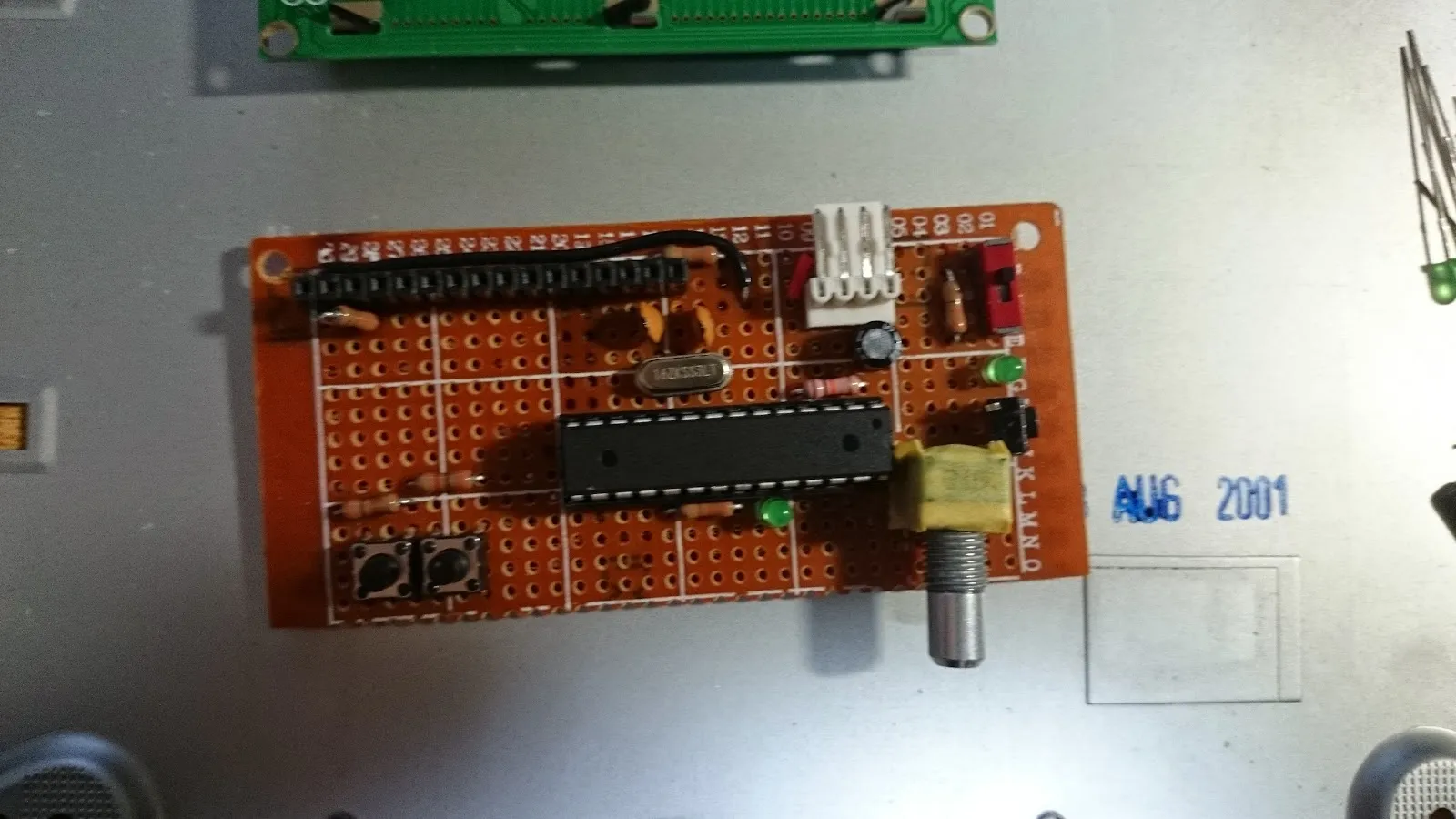
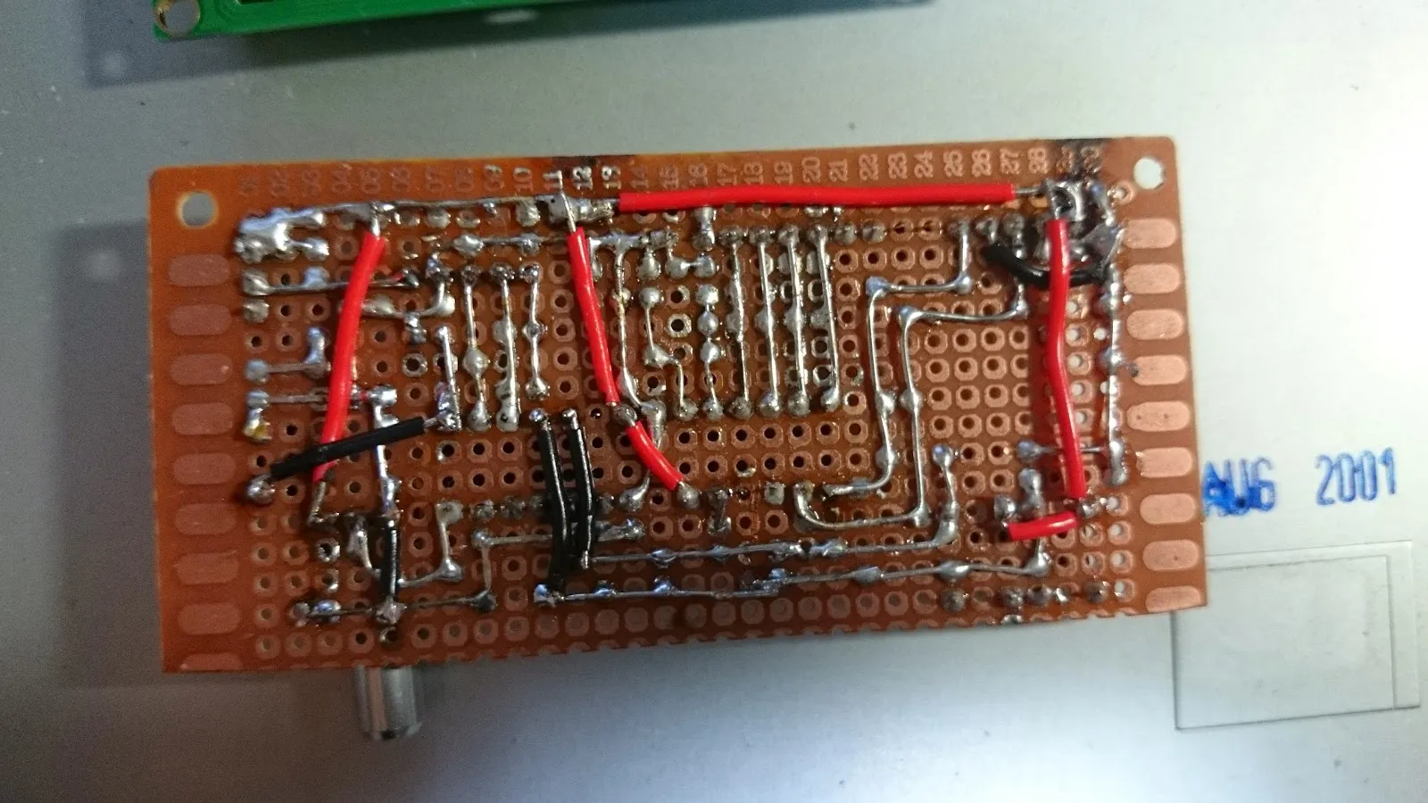
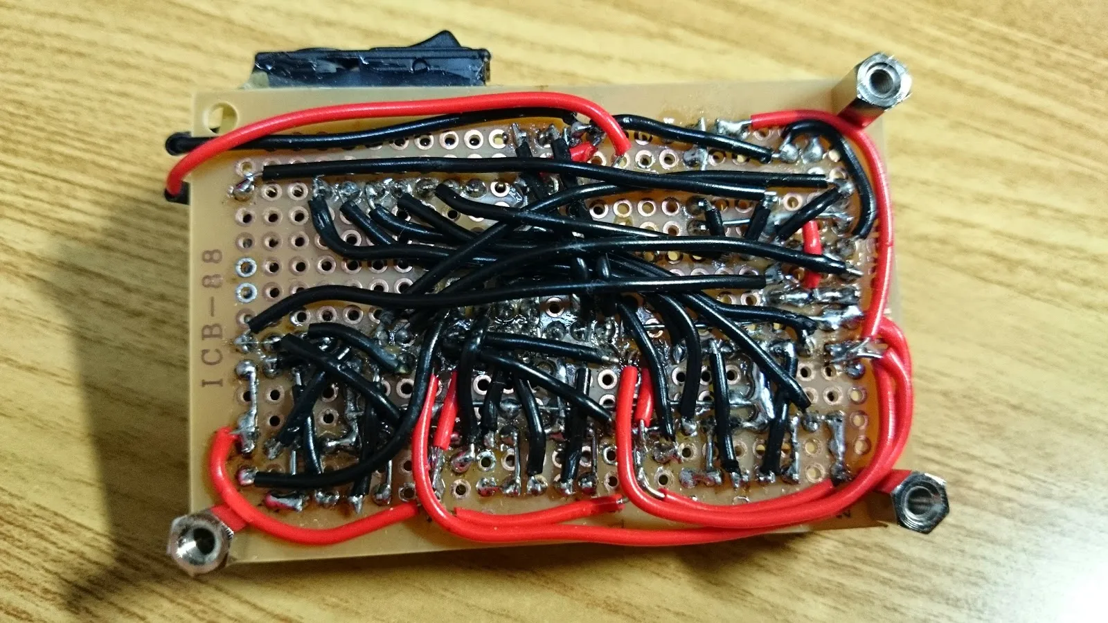
Soldering Time
Breadboard is not stabe, so time to do some dirty job
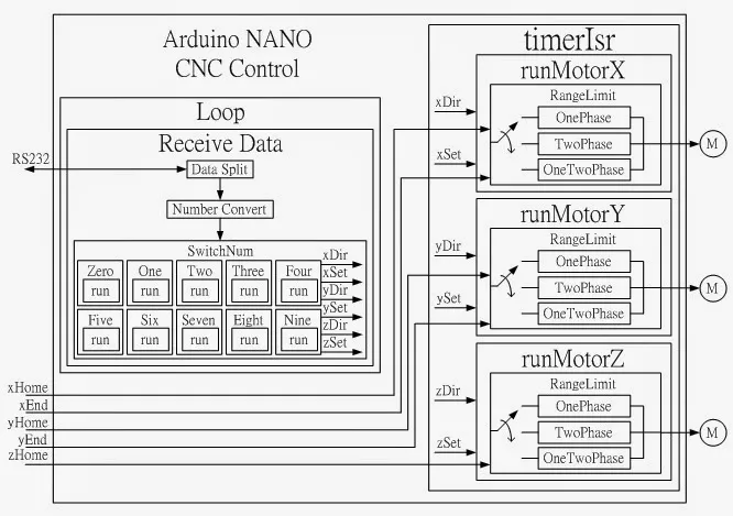
Some System Details
Firmware
The definition of excitation modes for stepper motors: 1-phase excitation, 2-phase excitation, and 1-2 phase excitation, can be conveniently controlled by defining them as a const array.
Some MCU port define and timer setup. The function GoHome() initializes the 3 axes to return to their origin point whenever the machine is started. Lines 7 and 8 initialize the timer interrupt, and line 9 informs the LCD control board that it can start transmitting data when the machine is turned on.
Every step must be completed before executing the next command, otherwise the machine may move on to the next stroke before completing the previous one.
This code directly controls the motor to move to its end and stops when it reaches the limit switch. Only the X-axis has «2 because the X-axis motor is connected starting from pin 2 and requires an initial shift for control. PORTD directly outputs to the motor command.
This code controls the motor to move a certain distance, and when the distance is reached, CNC.xOk=true is set to execute the next drawing command.
This code limits the movement of the motor using limit switches. PIND is used to read the status of the pins, and line 5 extracts the specific pin status using a mask. For the Z-axis, as it has only one limit switch, the distance of movement is limited using a counter on the other end.
Single-phase excitation for a stepper motor.
And just like that, amidst the neon lights and bustling streets of Tokyo, I discovered that real innovation doesn’t always require the newest tech; sometimes, it’s all about the art of the hustle, the spirit of resourcefulness, and a dash of Stark-inspired audacity. Keep it crafty, folks.

